|
Diagonal Forces
For science teachers, the central idea behind building
an effective Paper Bridge is vectors.
All bridges must deal with forces in two dimensions
-- the load is vertical, while the bridge is stretched
between two horizontally, separated support points.
This means that the paper has to bear diagonal forces.
To design a bridge with the best ratio of strength to
weight of paper used, students need to understand how
these diagonal forces work.
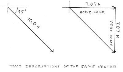
To describe a force that might act on the sheet of
paper used for the bridge, we need two pieces of
information:
how great the force is, and what direction
it acts in. We can state a magnitude and an
angle (“10 Newtons diagonally downward
to the right at 45 degrees”), or we can state
components in two separate directions
(“About 7 Newtons to the right and 7 Newtons downward”).
In either case this pair of numbers is mathematically
called a vector.
A powerful tool for understanding these forces is
to draw vector diagrams, where a vector
is an arrow that point in the force’s direction
and has a length proportional to the forces’ magnitude.
From the method of “seeing the force”
as wrinkles
in the paper, even in the uncut piece of paper,
we can immediately see a fundamental aspect of the forces
in this design challenge: as solid-mechanics theory
will attest, tensile forces in a flexible material run
in straight lines between connection points. A
“connection point” is either a support point,
a load attachment, or a “Y” branching point
within the paper if you cut it in that shape. Unless
you design a T-shaped bridge, the forces in the paper
are always diagonal, so in addition to vertical tension,
the paper must support horizontal tension as well.
But how much can it bear?
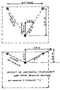
Combining the wrinkles-in-the-paper insight with the
component diagram vectors, we can answer this question.
Since the forces line up with the connection points,
the relation between the horizontal and vertical force
components in a segment of the paper is the same
as the ratio of the horizontal and vertical distances
between its attachment points.
For the two sides of the bridge, the total of vertical
force components is known: it’s the weight of
the water bottle. If the bridge is symmetrical, each side
gets half. So then the horizontal tension component will
be half the load weight, divided by the slope
of the segment of paper between attachment points. On
the diagram, rather than having to understand “dividing
by the slope,” we can simply see that the size of
the horizontal component is whatever it takes, at
the given slope, to make the diagonal vector long enough
that its vertical component is the required value—its
share of the weight of the water bottle.
With both vertical and horizontal components known,
the total (diagonal) tension force can be found
either by the Pythagorean theorem (the square root of
the sum of squares of the two components) or can be
estimated by using trigonometry, which involves measuring
the vectors drawn to call directly on the diagram. Shallow
slopes in these circumstances will start to give very
high horizontal tension components. The T-shaped bridge,
which theoretically has zero slope, demands an infinite
horizontal tension component. This is why we see these
bridges fail in the Student
Work video.
|